Example Applications
This section provides an overview of the TI 15.4-Stack out-of-box example applications and instructions on how to run them.
The TI 15.4-Stack-based star network consists of two types of logical devices: the PAN-Coordinator, and network devices (sleepy or nonsleepy). This separation of the device types derives from the IEEE 802.15.4 specification. The TI 15.4-Stack can be configured in either of the two roles by the application. The PAN-Coordinator is the device that starts the network, is the central node in the star network, and allows other devices to join the network. The network devices join the network and always communicate with the PAN-Coordinator.
The collector example application demonstrates how to implement a PAN-Coordinator device, while the sensor example application demonstrates how to implement the network devices.
The example applications provided in the TI 15.4-Stack are developed for the CC13x0 platform. In addition, the Linux example applications for the external host (AM335x) + MAC coprocessor configuration is included in the TI 15.4-Stack Linux SDK installer. All sample applications described in this section are intended to run on the CC13x0 LaunchPad platform. The Linux example application is described in the TI 15.4-Stack Linux Developer’s Guide included in the TI 15.4-Stack Linux SDK installer.
The following hardware is required to run the TI 15.4-Stack OOB example applications:
- Two CC13x0 LaunchPad development kits (https://www.ti.com/tool/launchxl-cc1310)
- Optional – Two LCD BoosterPack™ modules (https://www.ti.com/tool/430boost-sharp96)
The OOB example applications are configured to operate in the nonbeacon configuration with security enabled. See Configuration Parameters to understand the various parameters that application developers can configure to use the various configuration settings of the example applications.
Note
In the following sections, the project names for CC1310 and CC1350 platforms are referred to as CC13x0. Replace x with either 1 or 5 depending on the wireless MCU being used.
Collector Example Application
This example project implements a collector device: the PAN-Coordinator for the network. This device creates the TI 15.4-Stack network, allows sensor devices to join the network, collects sensor information sent by devices running the sensor example application, and tracks if the devices are on the network or not by periodically sending tracking request messages.
Running the Application
Perform the following steps to run the OOB collector example application.
Import the collector_cc13x0lp project as described in Importing SDK Projects.
After importing, configure the following settings in the config.h file. To configure the settings on the collector application project: Select the collector_cc13x0lp project in the CCS Project Explorer window. Find the config.h file, as shown in Figure 50..
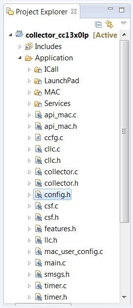
Figure 50. Collector Example Application Folder Project Explorer View
Set CONFIG_PAN_ID to the desired PAN ID.
Set CONFIG_PHY_ID according to region of interest:
For a US or 915-MHz band of operation, use the OOB CONFIG_PHY_ID settings as:
/*! Setting for Phy ID */
#define CONFIG_PHY_ID (APIMAC_STD_US_915_PHY_1)
For ETSI PHY for Europe (or 868-MHz band operation), configure the CONFIG_PHY_ID parameter:
/*! Setting for Phy ID */
#define CONFIG_PHY_ID (APIMAC_STD_US_915_PHY_3)
For China or 433-MHz band of operation, configure CONFIG_PHY_ID as:
/*! Setting for Phy ID */
#define CONFIG_PHY_ID (APIMAC_GENERIC_CHINA_433_PHY_128)
Note
Each PHY also has a SimpleLink Long Range, (SLM), mode of operation. This mode gives extended range, and has a data rate of 5kbps. The SLM PHY ID’s are:
- APIMAC_GENERIC_US_LRM_915_PHY_129
- APIMAC_GENERIC_CHINA_LRM_433_PHY_130
- APIMAC_GENERIC_ETSI_LRM_863_PHY_131
Set the preferred channel of operation in the CONFIG_CHANNEL_MASK parameter:
/*!
Channel mask used when CONFIG_FH_ENABLE is false
Each bit indicates if the corresponding channel is to be
scanned First byte represents channel 0 to 7 and the last byte represents channel 128 to 135
*/

#define CONFIG_CHANNEL_MASK { 0x0F, 0x00, 0x00, 0x00, 0x00, 0x00, \
0x00, 0x00, 0x00, 0x00, 0x00, 0x00, \
0x00, 0x00, 0x00, 0x00, 0x00 }
The channel numbers available in each band follow:
- 902 to 928 MHz (50 kbps): 0 to 128, such as when
CONFIG_PHY_ID = APIMAC_STD_US_915_PHY_1 - 863 to 870 MHz (50 kbps): 0 to 33, such as when
CONFIG_PHY_ID = APIMAC_STD_ETSI_863_PHY_3 - 433 to 434 MHz (50 kbps): 0 to 6, such as when
CONFIG_PHY_ID = APIMAC_GENERIC_CHINA_433_PHY_128
- 902 to 928 MHz (50 kbps): 0 to 128, such as when
In addition to the preceding configuration settings, note that when the devices join the network, the collector application configures the joining devices on how often to report the sensor data. To change or configure the interval at which the joining sensor devices report the sensor data, set the parameter CONFIG_REPORTING_INTERVAL to the desired value in milliseconds in the collector.c file. By default, the sensor reporting interval is set to 90 seconds, as shown by the following code snippet from the collector.c file:
/* Default configuration reporting interval, in milliseconds */
#define CONFIG_REPORTING_INTERVAL 90000
In the CCS Project Explorer, select the collector_cc13x0lp project.
Right-click on the collector_cc13x0lp project, and select the Build option. This builds the collector application project.
Download the project onto the CC13x0 LaunchPad by selecting Debug from the Run tab (see Figure 51.).
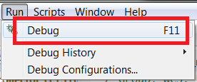
Figure 51. Debug Option
Terminate the debug session when the download is complete.
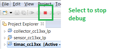
Select Terminate Option
If the AUTO_START compile flag is enabled, press BTN-1 to start the collector. The red LED on the LaunchPad turns on, and the display on the LCD should appear as in Figure 53..
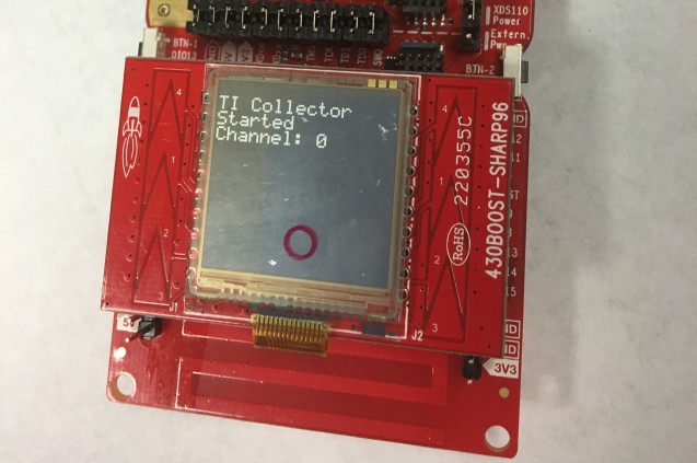
Figure 53. LCD Display (1 of 2)
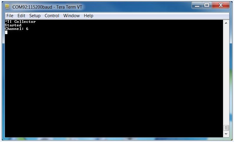
Figure 54. Hyperterminal When Collector is Started
Note
If you want to use LCD BoosterPack, remove USE_UART_PRINTF in the predefined symbols.
Press the BTN-2 button on the collector LaunchPad to allow new devices to join the network. Pressing the BTN-2 a second time closes the network, and new devices are not be able to join the network. Press button 2 a third time to allow new devices to join the network. When the network is open to new devices, the red LED blinks; when it does not blink, the network is closed to new devices. After the sensor successfully joins the network, the LCD on the collector LaunchPad is as shown in Figure 55..
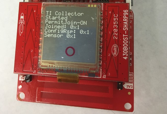
Figure 55. LCD Display (2 of 2)
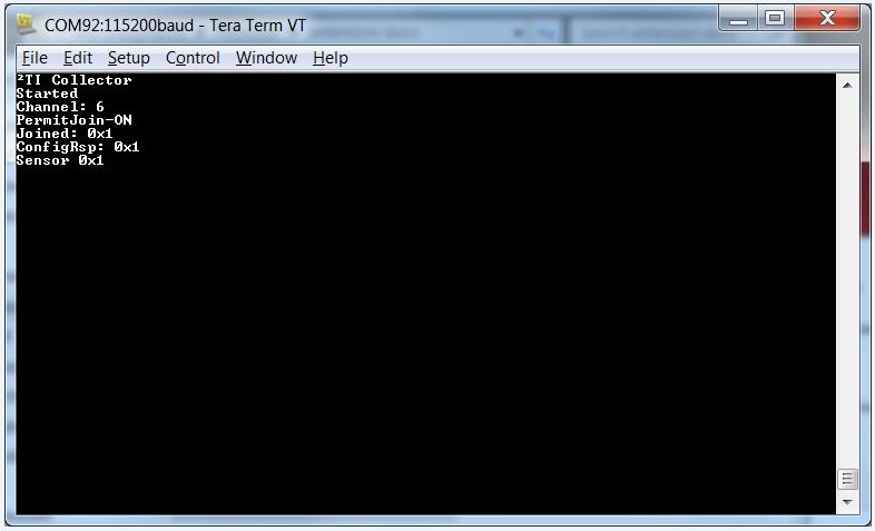
Figure 56. Hyperterminal When Sensor Joins Collector
Note
For instructions on programming and running the sensor application, see Sensor.
Sensor
This sample project implements a sensor, the end device which reads sensor information and sends it to the coordinator at a configured interval.
Running the Application
Perform these steps to run the out-of-box Sensor Example Application.
Import the sensor_cc13x0lp project, as described in Importing SDK Projects.
After importing, configure the following settings in the config.h file. To configure the settings on the sensor application project:
Select the sensor_cc13x0lp project in the CCS Project Explorer window.
Find the config.h file, as shown in Figure 57..
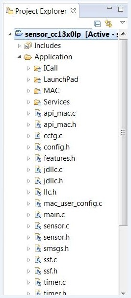
Figure 57. Config.h File
Set #define CONFIG_PAN_ID to the desired value to match the collector.
Set the Phy ID according to region of interest:
For a US or 915-MHz band of operation, use the OOB CONFIG_PHY_ID settings:
/*! Setting for Phy ID */
#define CONFIG_PHY_ID (APIMAC_STD_US_915_PHY_1)
For ETSI PHY for Europe (or 868-MHz band operation), configure the CONFIG_PHY_ID parameter:
/*! Setting for Phy ID */
#define CONFIG_PHY_ID (APIMAC_STD_US_915_PHY_3)
For China or 433-MHz band of operation, configure CONFIG_PHY_ID as::
/*! Setting for Phy ID */
#define CONFIG_PHY_ID (APIMAC_GENERIC_CHINA_433_PHY_128)
Set the preferred channel of operation (matching the collector) in CONFIG_CHANNEL_MASK:
/*!
Channel mask used when CONFIG_FH_ENABLE is false
Each bit indicates if the corresponding channel is to be
scanned First byte represents channel 0 to 7 and the last byte represents channel 128 to 135
*/

#define CONFIG_CHANNEL_MASK { 0x0F, 0x00, 0x00, 0x00, 0x00, 0x00, \
0x00, 0x00, 0x00, 0x00, 0x00, 0x00, \
0x00, 0x00, 0x00, 0x00, 0x00 }
The channel numbers available in each band follow:
- 902 to 928 MHz (50 kbps): 0 to 128, such as when
CONFIG_PHY_ID = APIMAC_STD_US_915_PHY_1 - 863 to 870 MHz (50 kbps): 0 to 33, such as when
CONFIG_PHY_ID = APIMAC_STD_ETSI_863_PHY_3 - 433 to 434 MHz (50 kbps): 0 to 6, such as when
CONFIG_PHY_ID = APIMAC_GENERIC_CHINA_433_PHY_128
Note
Each PHY also has a SimpleLink Long Range, (SLM), mode of operation. This mode gives extended range, and has a data rate of 5kbps. The SLM PHY ID’s are:
- APIMAC_GENERIC_US_LRM_915_PHY_129
- APIMAC_GENERIC_CHINA_LRM_433_PHY_130
- APIMAC_GENERIC_ETSI_LRM_863_PHY_131
- 902 to 928 MHz (50 kbps): 0 to 128, such as when
Build the stack project, then connect a LaunchPad to the PC, and call it sensor-launchpad.
Download the stack project onto the sensor-launchpad, and terminate the debug session when the download is finished.
Build the sensor application project and download it onto the CC13x0 LaunchPad using the method previously used to download the stack and terminate the debug session once the download is complete.
Terminate the debug session when the download is complete. The initial state of the LCD before the sensor joins a network is as shown in Figure 58..
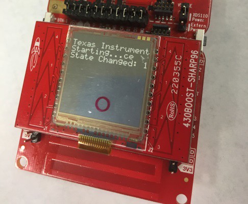
Figure 58. LCD Sensor Display (1 of 2)
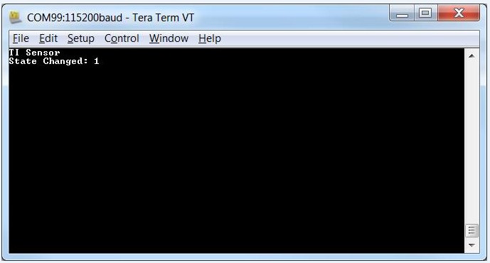
Figure 59. Hyperterminal When Sensor is Powered Up
After the sensor successfully joins the network, the LCD on sensor LaunchPad is as shown in Figure 60..
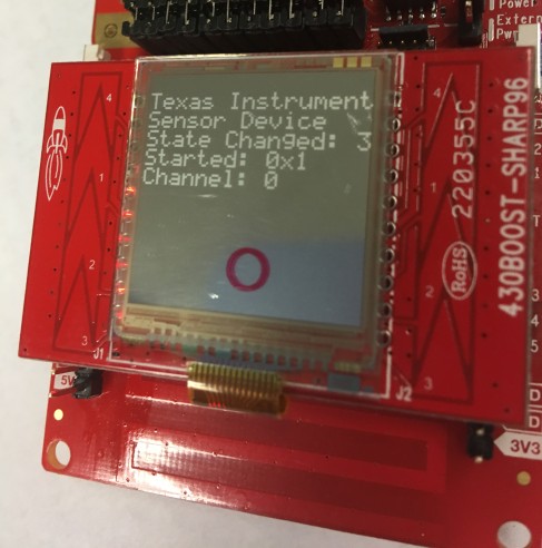
Figure 60. LCD Sensor Display (2 of 2)
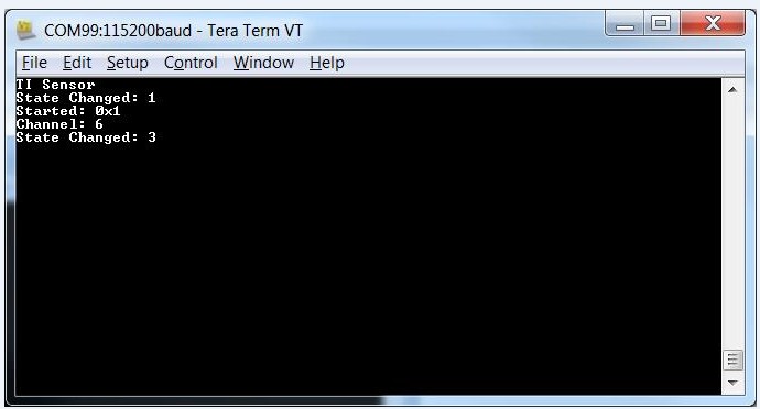
Figure 61. Hyperterminal When Sensor Joins The Network
Note
After the sensor node has successfully joined the network, it receives a configuration request message from the collector application. The node then configures the time interval on how often to report the sensor data to the collector application, and how often to poll for buffered messages in case of sleepy devices. After receiving the configuration request message, the green LED toggles whenever the device sends the message.
OAD Projects
The Sensor and Collector applications have an oad variation of the project named sensor_oad_cc1350lp and collector_oad_cc1350lp respectively. These projects are for use when performing a BLE OAD. Refer to the Bluetooth Low Energy Software Developer’s Guide for more information on BLE OAD
Running Over-the-Air-Download Example Applications
The Over-the-Air-Download example demonstrates how TI 15.4 images can be downloaded to the device using Bluetooth Low Energy (BLE) on dual band devices such as TI CC1350. The device must first be flashed with OAD capable BLE image and then by using BLE upload a 15.4 image.
The following steps must be performed to get OAD working:
You need two 1350 Launch-Pads (LPs): one will be the downloader and the other will be the device.
- Get BLE device monitor working https://processors.wiki.ti.com/index.php/BLE_Device_Monitor_User_Guide . Note that you will need to flash the LP going to be used as downloader with host_test images. TI Smart RF Flash Programmer 2 can be used to flash hex files on to the LP. These are available in the hexfiles ble_oad folder. Ensure to flash the host_test_cc1350lp_stack hex file first. Then uncheck erase in the smart RF Flasher tool. Then flash host_test_cc1350lp_app hex file. The LP attached to device monitor will be the downloader.
- Then flash simple_peripheral_cc1350lp_merged.hex file on to the device using Smart RF Flasher. This includes the OAD capable BLE stack, BLE app and Boot Image Manager (BIM) merged into a single hex file. The hex file is available in the hexfiles ble_oad folder. If instead of using the pre-built hex, it can also be built from the BLE project. Steps for this can be found in the BLE OAD User guide found in the BLE documentation folder.
- Upon reset of the device, the BLE advertisement “Simple BLE Peripheral” should now be viewable in the device monitor. If not try clicking on scan button in device monitor application or press the reset button on the device LP. Establish BLE connection with the device from the monitor by double clicking on the device in the monitor. You should see OAD as one of the services supported by the BLE device now.
- Next go to file and choose OAD in the device monitor application. Then set image type to 2 i.e. stack and load simple_peripheral_cc1350lp_no_bim.hex. If instead of using the pre-built hex file, it is required to be created from the BLE project, then please follow the instructions in the BLE OAD User Guide available in the BLE documentation folder. This image has the OAD capable BLE stack + app without BIM. Then the number of blocks per transfer can be chosen. Setting it to the lowest is the slowest but the most reliable. Then start and complete the OAD.
- Wait for device to reset and for BLE advertisement “Simple BLE Peripheral” to show up on the device monitor. If it does not show up, try pressing the reset button on the LP or click scan on the device monitor application. Once the advertisement appears on the device monitor, the device is capable of performing OAD of any image.
- Now by following steps similar to 3 and 4, download prebuilt 15.4 image sensor_oad_cc13x0lp.hex or collector_oad_cc13x0lp.hex from the hexfiles ble_oad folder depending on the role of the 15.4 device. However, note that the image type must be set to 1 i.e. application. If the images are required to be built from project, please use the sensor_oad or the collector_oad projects to generate the hex file. Opening and building the project is similar to how it is done for the regular sensor and collector projects. The default configuration for the oad projects generates an oad compatible 15.4 image.
- Wait for OAD to complete and the device to reset. The BLE advertisement from the device will no longer be observed in the monitor. The 15.4 stack image should now be running on the device.
- To switch back to OAD capable BLE image, press both left and right buttons at the same time.
FH Conformance Certification Application Example
The FH conformance certification example application is provided to enable users to perform an FCC or ETSI compliance tests related to channel occupancy. FCC regulations states that a channel hopping device can transmit at a high power up to 30 dbm if using more than 50 channels for hopping and ensuring that the average channel occupancy time over a 20 second period is less than 400 ms per channel [FCC]. To verify this behavior, test labs perform a channel occupancy test [FCCTest]. The actual rate at which a node shall occupy a channel depends on the application traffic. To account for a generic application profile, a back-to-back data transmission mode can be used for the compliance test.
To enable back-to-back transmissions from a device to the collector, the following configurations must be set:
- CERTIFICATION_TEST_MODE = true
- CONFIG_FH_ENABLE = true
The rest of the configurations can be set to default. In this mode, the device joins the collector and transmits back to back frames to the collector. The collector does not generate any frames but simply acknowledges the transmissions from the sensor. The frames can be capture using a spectrum analyzer to perform the channel occupancy test. The mode can also be used for ETSI testing. Note that the example application is only provided for a general guidance and for ease in performing regulation tests. Any other alternate application profiles to better reflect the application needs can also be used for compliance tests.
[FCC] FCC Part 247 - 47 CFR 15.247 - Operation within the bands 902 to 928 MHz, 2400 to 2483.5 MHz, and 5725 to 5850 MHz
[FCCTest] C63.10-2013 - American National Standard of Procedures for Compliance Testing
Configuration Parameters
Table 18. lists the various configuration parameters available for the collector and sensor applications. Features.h allows the user to compile only the features needed for the mode of operation needed, which facilitates memory savings. Out of the box FEATURE_ALL_MODES is defined which enables all modes of operation and FEATURE_MAC_SECURITY is define which enable security.
The user can only define one of the features among the following options.
- FEATURE_FREQ_HOP_MODE – frequency hopping mode of operation
- FEATURE_BEACON_MODE – beacon mode of operation
- FEATURE_NON_BEACON_MODE – nonbeacon mode of operation
- FEATURE_MAC_SECURITY – enable security
- FEATURE_BLE - enable uBLE stack operations
| Config Parameter | Description |
|---|---|
| Common Configuration Parameters | |
| CONFIG_SECURE | Turn security ON or OFF This value should match for both collector and sensor. |
| CONFIG_PAN_ID | Used to restrict the network to a certain PAN ID. If left as 0xFFFF, the collector starts with PAN ID 0x0001. If this parameter is set to a certain value for the collector, the value should be set to either the same value or 0xFFF for the sensor application, so that the sensor joins the intended parent. |
| CONFIG_FH_ENABLE | Used to turn frequency-hopping operation ON or OFF |
| CONFIG_MAX_BEACONS_RECD | Maximum number of received beacons to filter after the scan request is sent out |
| CONFIG_LINKQUALITY | The device responds to enhanced-beacon requests if mpduLinkQuality is equal to or higher than this value. |
| CONFIG_PERCENTFILTER | The device randomly determines if it is to respond to enhanced- beacon requests based on meeting this probability (0 to 100%). |
| CONFIG_SCAN_DURATION | Scan duration for scan request |
| CONFIG_MAX_DEVICES | Maximum number of children for coordinator |
| CONFIG_MAC_BEACON_ORDER | Beacon order according to mode of operation: For nonbeacon and frequency-hopping modes, set this value to 15 for both collector and sensor. For beacon mode, this value can be from 1 to 14, and must match for both collector and sensor. |
| CONFIG_MAC_SUPERFRAME_ORDER | Superframe order, according to mode of operation: For nonbeacon and frequency-hopping modes, set this value to 15 for both collector and sensor. For beacon mode, this value can be from 1 to 14, and must match for both collector and sensor. |
| CONFIG_CHANNEL_PAGE | The channel page on which to perform the scan |
| CONFIG_PHY_ID | PHY ID corresponding to the PHY descriptor to use based on region of operation |
| KEY_TABLE_DEFAULT_KEY | Default security key |
| CONFIG_CHANNEL_MASK | For the collector application: Each bit indicates if the corresponding channel is to be scanned. The first byte represents channels 0 to 7, and the last byte represents channels 128 to 135. In FH mode: represents the list of channels excluded from hopping. It is a bit string with LSB representing Ch0; for example, 0x01 0x10 represents Ch0 and Ch12 are excluded. Currently, the same mask is used for unicast and broadcast-hopping sequences. For the sensor application: For nonfrequency-hopping configuration: Channel mask – each bit indicates if the corresponding channel is to be scanned. The first byte represents channels 0 to 7, and the last byte represents channels 128 to 135. In FH mode: If CONFIG_RX_ON_IDLE = TRUE: represents the list of channels excluded from hopping. It is a bit string with LSB representing Ch0; for example, 0x01 0x10 represents Ch0 and Ch12 are excluded. The same mask is used for both unicast and broadcast-hopping sequences. If CONFIG_RX_ON_IDLE = FALSE: represents the list of channels to be used for hopping. It is a bit string with LSB representing Ch0; for example, 0x01 0x10 represents Ch0 and Ch12 are used for hopping. In this mode, the node hops in increasing order of the chosen channel. |
| FH_ASYNC_CHANNEL_MASK | List of channels to target the async frames. It is represented as a bit string with LSB representing Ch0; for example, 0x01 0x10 represents Ch0 and Ch12 are included. It must cover all channels that could be used by a target device in its hopping sequence. Channels marked beyond number of channels supported by PHY Config are excluded by stack. To avoid interference on a channel, remove it from async mask and add it to the exclude channels (CONFIG_CHANNEL_MASK). |
| CONFIG_DWELL_TIME | Duration of the unicast and broadcast slot of the node (in ms) |
| CONFIG_FH_NETNAME | Default value for FH PIB attribute netname |
| CONFIG_TRANSMIT_POWER | Value for transmit power in dBm. Default value is 14, allowed values are any value between 0 dBm to 14 dBm in 1 dB increments, and - 10 dBm. When the nodes in the network are close to each other, lowering this value helps reduce saturation. |
| CERTIFICATION_TEST_MODE | If set to true, the device joins the collector and transmits back-to- back frames to it. The collector does not generate any frames, but simply acknowledges the transmissions from the sensor. The frames can be captured using a spectrum analyzer to perform the channel occupancy test. The mode can also be used for ETSI testing. The example application is only provided for a general guidance and for ease in performing regulation tests. NOTE: The FH conformance certification example application is provided to allow users to perform a FCC or ETSI compliance tests related to channel occupancy. FCC regulations state that a channel hopping device can transmit at a higher power of up to 30 dbm if it uses more than 50 channels for hopping and ensures that the average channel occupancy time over a 20 second period is less than 400 ms per channel [FCC]. To verify this behavior, test labs perform a channel occupancy test [FCC Test]. The actual rate at which a node occupies a channel depends on the application traffic. To account for a generic application profile, a back-to-back data transmission mode can be used for the compliance test. To enable back-to-back transmissions from a device to the collector, the following configurations are to be set: • CERTIFICATION_TEST_MODE = true • CONFIG_FH_ENABLE = true In this mode, the device will join the collector and transmit back to back frames to collector. Collector will not generate any frames but would simply acknowledge the transmissions from sensor. The frames can be capture using a spectrum analyzer to perform the channel occupancy test. The mode can also be used for ETSI testing. Note that the example application is only provided for a general guidance and for ease in performing regulation tests. Any other alternate application profiles to better reflect the application needs can also be used for compliance tests. [FCC] FCC Part 247 - 47 CFR 15.247 - Operation within the bands 902 to 928 MHz, 2400 to 2483.5 MHz, and 5725 to 5850 MHz [FCCTest] C63.10-2013 - American National Standard of Procedures for Compliance Testing |
| FH_NUM_NON_SLEEPY_NEIGHBOURS | The number of non-sleepy end devices to be supported. This value is limited to 50. This setting can be used for memory savings so that the stack allocates memory proportional to the number of end devices requested. |
| FH_NUM_SLEEPY_NEIGHBOURS | The number of sleepy end devices to be supported. This value is limited to 50. This setting can be used for memory savings so that the stack allocates memory proportional to the number of end devices requested. |
| Collector-Specific Configuration Parameters | |
| CONFIG_COORD_SHORT_ADDR | Short address for coordinator |
| CONFIG_TRICKLE_MIN_CLK_DURATION | The minimum trickle timer window for PAN advertisement and PAN configuration frame transmissions. Default is 0.5 minute. TI recommends setting this to half of the PAS/PCS MIN timer. |
| CONFIG_TRICKLE_MAX_CLK_DURATION | The maximum trickle timer window for PAN advertisement and PAN configuration frame transmissions. Default is 16 minutes. |
| CONFIG_FH_PAN_SIZE | Default value for PAN size PIB |
| CONFIG_DOUBLE_TRICKLE_TIMER | Enables doubling of PA or PC trickle time: used when the network has non-sleepy nodes and there is a requirement to use PA or PC to convey updated PAN information. |
| Sensor-Specific Configuration Parameters | |
| CONFIG_MAX_DATA_FAILURES | Maximum number of data failures before considering sync loss (this parameter is available only for the sensor) |
| CONFIG_PAN_ADVERT_SOLICIT_CLK_DURATION | PA solicit trickle timer duration in ms (this parameter is available only for the sensor) |
| CONFIG_PAN_CONFIG_SOLICIT_CLK_DURATION | PAN configuration solicit trickle timer duration in ms (this parameter is available only for the sensor) |
| CONFIG_FH_START_POLL_DATA_RAND_WINDOW | FH poll/sensor message start time randomization window (this parameter is available only for the sensor) |
| CONFIG_POLLING_INTERVAL | Polling interval in ms (this parameter is available only for the sensor) |
| CONFIG_FH_MAX_ASSOCIATION_ATTEMPTS | Maximum number of attempts for association in FH mode after reception of a PAN configuration frame (this parameter is available only for the sensor) |
| CONFIG_SCAN_BACKOFF_INTERVAL | Scan back-off interval in ms (this parameter is available only for the sensor) |
| CONFIG_RX_ON_IDLE | Used to indicate if a device is sleepy or nonsleepy: FALSE for sleepy, and TRUE for nonsleepy (this parameter is available only for the sensor). |
| CONFIG_ORPHAN_BACKOFF_INTERVAL | Delay between orphan notifications |
| CONFIG_BLE_SUPPORT | Enables BLE advertisements in the application |
| CONFIG_URL_TOGGLE | Enables toggling of URLs contained in BLE advertisement beacons |
| FH_LRM_COORD_SHORT_ADDR | Coordinator Short Address When Operating in LRM mode with FH Enabled. This value will be ignored in all other modes |
| CONFIG_RANGE_EXT_MODE | Range Extender Mode setting. The following modes are available. APIMAC_NO_EXTENDER - does not have PA/LNA, APIMAC_HIGH_GAIN_MODE - high gain mode. To enable CC1190, use #define CONFIG_RANGE_EXT_MODE APIMAC_HIGH_GAIN_MODE |
Coprocessor
The coprocessor project is used to build a MAC coprocessor device that works with a host processor in a 2-chip scenario. The coprocessor provides an interface to the TI 15.4-Stack protocol stack, full-function MAC capability over serial interface to the application running on the host. This device, programmed with the coprocessor application and the TI 15.4-Stack protocol stack, allows the addition of TI 15.4-Stack wireless functionality to systems that are not suited to single-chip solutions. A prebuilt hex file for the coprocessor is provided in the SDK. If changes are needed, such as an addition of a custom API command, the coprocessor project can be used to generate a new hex file.
Linux Example Applications
A brief description of the Linux example applications follows. For more detail, refer to the documentation included with the TI 15.4-Stack Linux SDK installer at https://www.ti.com/tool/SIMPLELINK-CC13X0-SDK.
Linux Collector and Gateway Application
These two example applications are provided inside the TI 15.4-Stack Linux SDK installer, a component of the TI 15.4-Stack. The Linux collector example application interfaces with the CC13x0 running the coprocessor and stack image through a UART. The Linux collector example application provides the same functionality as the embedded collector application, while also providing a socket server interface to the Linux gateway application. The Linux gateway application implemented within the Node.js framework connects as a client to the socket server created by the Linux collector example application, and establishes a local web server to which the user can connect through a web browser (in the local network), and monitor and control the network devices. The collector and gateway applications can be great starting points for creating IOT applications. For more details, refer to the TI 15.4-Stack Linux Developer’s Guide included with the TI 15.4-Stack Linux SDK installer.
Linux Serial Bootloader Application
This example application is included inside the TI 15.4-Stack Linux SDK installer. This application provides the capability to upgrade the firmware of the CC13x0 MCU through the CC13x0 ROM bootloader. For more details, refer to the TI 15.4-Stack Linux Developer’s Guide included with the TI 15.4-Stack Linux SDK installer.